I've recently built a Z80 based computer (RC2014) which was an interesting trip back down memory lane. It's based on a backplane and I knew I would damage something if it wasn't boxed up. So... time to get it boxed.
 |
| Amazon steel instrument case |
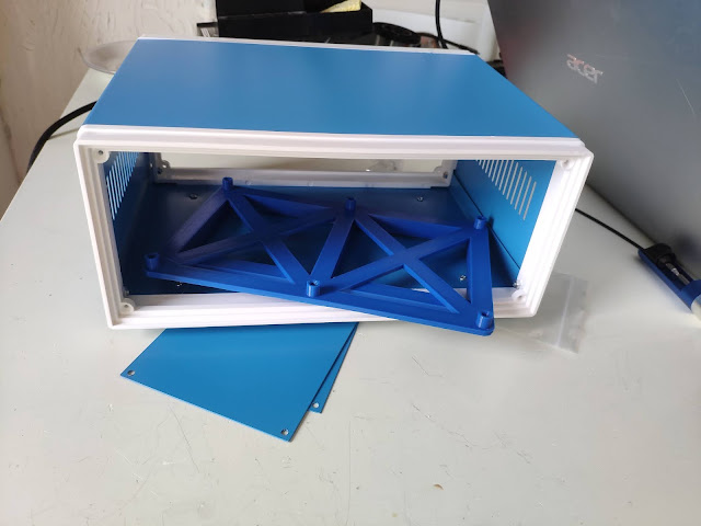
The steel box in the picture came from Amazon, it was just short of £25 and to be honest I can't see that amount of money there. It looks a little flimsy, but I'm sure it's good enough to do the job. There's a 3D printed cradle that the PCB bolts into, the cradle is simply superglued into the base of the box. The thin steel front and back panels won't be used.
 |
| 3D printed back panel |
The back panel is quite a busy affair, lots of connectors and switches on it; hopefully it will look quite neat when finished and everything will fit in the case properly. The Arduino female to female jumper leads in the background will be glued up into 3D printed shell housings to make 0.1" pitch connectors.
 |
| PCBs wired to the back panel ready for installation |
I printed out a spacer bar to join the PCBs together (blue strip at far end of PCBs), it locks into the hole in each corner and works quite well. If you're wondering why the bar is cranked down at the ends into a moustache shape, the two end boards have single row connectors and sit 0.1" further down and also 0.1" to the left of where a two row board would go. Took me a while to figure that out.
 |
| The joiner bar for the cards |
The switch near the top left replaces the jumpers on the Raspberry Pi terminal board so will allow the TX/RX lines from SIO(A) to either go to the Pi or out to the top FTDI interface on the right.
 |
| Rear panel installed |
The rear panel is quite busy, from left to right:
- FTDI 1: Connects to SIO(A) TX/RX lines if the terminal switch is on External
- FTDI 2: Connects to SIO(B) TX/RX lines permanently
- Reset button which is recessed to prevent being pushed by accident
- Power switch on the RC2014 main board
- Power socket on the RC2014 main board
- Terminal switch: In the left position it connects SIO(A) TX/RX lines to the FTDI1 socket. In the right position it connects the TX/RX lines to the Raspberry Pi. Note that the switch position for TX/RX to FTDI has a crossover as the Raspberry Pi board seems to swap these two pins for some reason
- HDMI socket from the Raspberry Pi terminal board
- USB socket to plug a keyboard into the Raspberry Pi terminal board
- RCA phono socket for composite video. I haven't wired this up yet and not in a hurry to
 |
| Front panel with plain logo |
The front panel has the duncanamps logo with 21 LEDs behind it. The silver 3D printed panel has a semi-translucent white logo, printed using the
Prusa MK3/S and the
Prusa Multi Material Unit (MMU2).
 |
| Finished front panel |
Total project cost for the case and connectors was around £40-£50, it really looks good now and will protect the RC2014 from being knocked around.


It's a really nice job Duncan. The box may have been pricey but it looks the part.
ReplyDeleteThanks! I'm pleased that the RC2014 is complete now, just need to work out what geeky thing to do next :)
DeleteWhat an interesting project! The RC2014 is a great example of retro computing. Love how everything is packaged up neatly. Keep sharing these amazing builds!"
ReplyDeleteFor The Eye Foundation Hospital in Bangalore:
"The Eye Foundation in Bangalore provides top-notch eye care with state-of-the-art facilities and a dedicated team. A great choice for comprehensive eye treatments
Eye Hospital in Bangalore